Team BangaloreRobotics - Deepak Narayanan
THESIS FOR
LASER CUTTING/ENGRAVING MACHINE – OPEN SOURCE
- Team BangaloreRobotics
INTRODUCTION
An Arduino
controlled CNC LASER ENGRAVER/CUTTER:
We
recently made a CNC Laser Engraver/ Cutter. The controller of the CNC machine
is Arduino. This was a very challenging and also a sophisticated project. The dimensions
of the machine are 1524*914*350 (all in mm). The power of the laser used in
this project was 100W. This became one of the most successful project and we
want to share it with everyone.

ARDUINO BOARD(pic)
The reason we did this project was to bring a
unique progress in the field of Robotics and show the world that how the
knowledge of Electronics & Electrical, Mechanical and Software can be
combined to design and build something fascinating. This has been a stepping
stone for our career.
WARNING & PRECAUTIONS:
As
this is one of the most interesting projects, we would suggest you to think several
times before making it. And this must be done under the guidance and
supervision of an expert. Working with a LASER
is very risky. A ray of laser which has a power >50mW can cause
permanent damage to your eyes, or may be to your skin accidentally. But here,
we are talking about 100W LASER. Probably
now you must understand the magnitude of the damage. DO NOT ALLOW KIDS, PETS OR ANY BEGINNER NEAR THE LASER. As a
precaution wear a pair of SAFETY GLASSES
for the suitable wavelength of the laser or you could attach a CAMERA inside and monitor the working
on a screen, which we would suggest it as the most ideal and safe method.
STEP 1: THE HARDWARE
The frame which you see in the pictures is
made of aluminum. The dimensions are 1524(length)*914(breadth)*350(height) all
in mm. the workspace we have allocated is around 900*600 both in mm. They are
welded at the joints. Basically, this looks like a cuboid and the rest of the
assemblies will be fit exactly into this frame.
STEP 2: X-Y PLANE

Y-PLANE

X-PLANE
The plane that has a back and fro movement is
the Y-Plane and the X-Plane is mounted on the Y-Plane, this has a horizontal
movement.
STEP 3: MOTORS AND DRIVERS

The motors used in this are NEMA 23. They are
3 phase stepper motors. Each motor has a driver for its respective axis. The 3 phase motors are really powerful
motors. The details about the motors are given below.
No. of motors required – 2
Step angle – 1.8o
Step angle accuracy - ± 5%
Resistance accuracy - ±10%
Inductance accuracy - ±20%
Holding torque – 10kg
Length – 51mm
STEP 4: SETTING UP THE LASER TUBE

The
laser tube is a very delicate thing. It must be handled with a great care, a
small crack on it could make the whole tube a waste. The tube will be placed on
the tube holders and has to properly aligned.
WORKING:
On one end of the tube, from where the laser
beam comes out, a mirror is fixed there. The mirror has to be aligned at an
angle of 45o, so that it reflects the beam to the second mirror. The
second mirror must also be aligned at angle of 45o so that beam goes
to the third mirror, which is located in the nozzle. After the beam reflects
from the third mirror, the beam is reflected vertically downwards into a
Plano-convex lens. And we get a clear focus of the beam on the surface. The
alignment has to be done with help of an expert.

MIRROR 1 (BURNT PAPER DUE TO THE POWER OF LASER)

MIRROR 2

MIRROR 3
STEP 5: ELECTRICAL SETUP
LASER SETUP:

The above shown is the setup for the
connection between Laser power supply and Laser (DSP).

In
the above picture shown, the stepper motors are connected to its respected axis
drivers.
STEP 6: MECHANICAL SETUP

The aluminum sheets are covered on all the
sides of the frame. These sheets protect the laser ray to go out and also give
a complete look to the system. There is a water pump used, the water travels
through the laser tube, acting as the coolant. On the other hand there is an
air pump used which is connected to the nozzle, when the laser is on it blows
away the fumes with a jet of force, so that the lens inside is protected and
does not get clouded.
STEP 7: POWER SUPPLIES


The Laser needs a
power supply of 220V. The power consumed by each stepper motor is 2.3V and 2.8A
current maximum. The main board that controls the stepper motor is Aurdino. A
H- bridge or a GRBL shield is connected to the Arduino board, the GRBL shield
controls the motors.
STEP 8: SOFTWARE
The main software we used was PHCAD and
Inkscape. Follow the steps below.
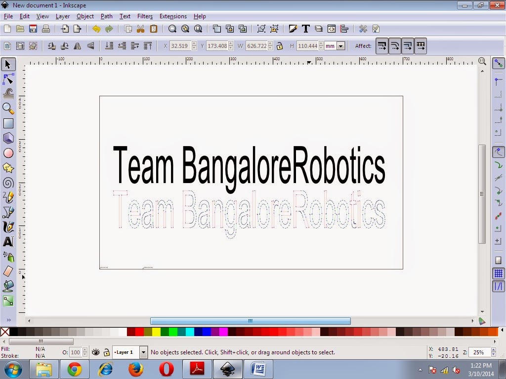
1. Open Inkscape and create a workspace of the required dimension.

2. Type a text or import the file
to be plotted.

3. Select the
text and click on Object to path

4. Click on Laser

5. Create the
output file in .nc format

6.
Finally,
STEP 9:Gcode Sender
1. Select the
required Port.

2. Browse for the
.nc file and click on Print

STEP 10: OUTPUT
ENGRAVINGS AND CUTTINGS


ACCIDENT:


posted by Deepak @ 11:33
1 Comments
![]()

1 Comments:
I am very Glad to see your informational Post! Just saw that laser cutter machine at the Maker Faire. How it is holding up for you? You use t for cutting versus engraving often. Also curious if you got Lightburn running on it too.
Post a Comment
Subscribe to Post Comments [Atom]
<< Home